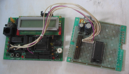
16 servo addon for handyboards without the expansion
Beginnings
When I got my handyboard, I realised that there were no servo ports on it. The expansion board had 6, but I didn't think that 6 servo ports were worth the price of the expansion.
I ended up making a fully reversible modification to my handyboard that gave me 16 servo ports costing a total of about $2, two of the motor ports and a digital input.
Concept
A servo motor doesn't just turn when we apply voltage. instead, it is a positional motor - it exerts effort to maintain a particular position. We tell it which position by supplying a string of pulses, where the time that the pulse is positive defines the position we want the motor to hold. 0.8ms is 90 degrees left, 1.5ms is center, and 2.2ms is 90 degrees to the right.
Digital input #9 is connected to a special pin on the 68HC11. It is connected to a bi-directional timer pin which can have its digital level read, throw an interrupt when it changes and record the time, be a digital output, or make a pulse that goes for a specific length of time (of either polarity), and throw an interrupt when the pulse ends!
I did a little bit of maths, and worked out that this timer has a resolution (or accuracy) of 500ns! this means 3,000 counts for center position - well within our maximum time of 65,535 counts. The fact that we can ask the 68hc11 to tell us when its done is great too - we can use this to trigger the pulse again without ever having to check if we need to start again!
Then I realised that this would supply the pulses too fast - servos like 15-30ms of 'dead time' between pulses so that they have time to think.
Instead of making the board wait until its ok to pulse again, I wondered if I could get it to pulse a different servo in that time instead - enter the 4514 ic.
The 4514 ic basically decodes 4 bits and sends the relevant one of 16 pins positive. Each motor port uses two bits - direction and enable. I decided that I wouldn't need more than two motor ports, and could use the other two to talk to the 4514.
The signals to the L293D are latched in the '374 next to them, which means that if we remove one L293D, we have four bits that we can program to do anything we want.
The four signals to the L293D chip are present on pins 1,2,9 and 10. (the two direction signals are also available inverted on pins 7 and 15, but they're not much use to us here.)
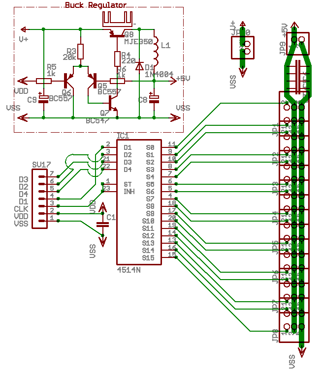
If we connect these four pins to the 4514's A,B,C and D inputs, along with ground and 5v, we should be able to programatically make any of the 4514's 16 outputs go positive!
The 4514 also has an INHIBIT input that, when driven positive will make all 16 outputs negative. If I connected this line to my timed pulse pin, I could select a servo using the motor port, pulse it with the timer, and then select the next servo and repeat. 16 servo pulses at 2.2ms is about 40ms all up - which is just within the dead zone tolerance of most servos. 16 pulses at 0.8ms is about 12ms which is cutting it fine, but acceptable.
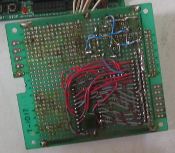
I pulled out the bottom L293D, and wired in the 4514 according to my plan with some pin headers from an old pc/isa super IO board, and wrote some software to control it.
After I had debugged my program, I went for a test with 12 servos plugged in. They all went crazy! Something was seriously wrong somewhere, but what was important at the time was They were all moving!
I probed around with my logic probe, and scanned through my code, and then the IC library code to try and work out what was going on. After much hair-pulling exasperation, I finally worked out that the PWM code for the motors kept running even if the motor was off...
You guessed it, the IC library's system interrupt that provides you with that nice heartbeat was re-selecting the servo every time around the loop. I did try hacking at the library, but eventually noticed a much easier way to do it.
The 4514 has 24 pins. 2 for power, 4 inputs, 16 outputs is 22, the INHIBIT line is 23, but what was the 24th pin? I had a look. The pin was marked STROBE, and a footnote in the manual said that this pin had to be positive for the chip to accept new input - otherwise it would remain latched.
I saw instantly that if I connected this directly to the INHIBIT pin, a new servo could only be selected while all ouputs were low - in the part of the cycle where my code had control of the motor port! While the outputs were enabled, the PWM circuitry's bamboozle would be blocked by the very signal that pulses the servos = perfect!
A test run of this minor change in configuration immediately confirmed my suspicions, and all 16 of my servos were then under complete programmatic control for the price of a 4514, two motor ports and digital input #9.
Testing revealed that the timer had higher accuracy than the servos themselves, with about 16-18 (depending on the servo brand) 'ticks' per degree of rotation - meaning that the approximate conversion from degrees to ticks was literally as simple as four shift left instructions, or a multiply by 16...
I refined my code as much as possible, and the interrupt routine is now composed of just 25 instructions.
I present the plans and my code to you below.
Schematic
16 servo extensionLegend:
- V+
- Unregulated supply from battery
- VDD
- Regulated, Logic 5v.
- VSS
- 0v, ground
- +5v
- High current output from buck regulator
- D1-4
- Output select data lines
- CLK
- Clock - latches data when 1, enables outputs when 0
Parts
- A ‘4514’ 4-to-16 line decoder
- A 16 pin DIL header plug
- A 4 pin SIL header plug
- 4 4x3 pin header blocks (I had to make these by combining 2x3 strips from spare IDE plugs)
- A piece of veroboard or project board to put the 4514 and servo connectors on
- A L293D Manual
- A 4514 Manual
- A working HandyBoard...
Building
Attach wires to pins 1,2,4,5,8,9,10,12,13 of the 16 pin DIL header. 4,5,12 and 13 are all ground so they can share a single wire.
Remove the lower L293D and put the 16 pin header in its place. This makes it easier to keep track of which wire is which.
connect pin 10 to input A on the 4514, pin 2 to B, pin 9 to C, and pin 1 to D. This isn't at all crucial, but it means that bits 2,3,6,7 correspond to A,B,C,D. This gives us the ability to use the output numbers in the 4514 manual, rather than having to work out the index/output mapping on our own.
connect INHIBIT and STROBE together, and then run a wire to one end of the 4 pin SIL plug. remove the adjacent pin as noted in the handyboard manual section on wiring sensors. plug this in to dig. in #9.
Set out the 2x3 pin headers so that you get 3 rows of pins, in groups of four columns with a space between each group. Servo plugs are a shade wider than 1/10" and if you put them all together, you will find it quite difficult to plug in more than a few servos.
Two rows are power rails for the servos - the center row and one outside row. The center row is +5v servo power, one of the outside rows will be ground, and the other row will be the 16 signals from the 4514. MAKE SURE you label them properly - there's nothing more humiliating than plugging every servo in backwards!
I recommend that you put a 100n or so MKT or ceramic capacitor between the power rails in each of the gaps, and a large (220uF+) electrolytic at one end. This will greatly reduce motor noise and increase the accuracy and reliability of both your servos and the handyboard itself
Pins 4,5,12,13 are ground from the hb, and pin 16 is +5v. connect the ground to the 4514 and the servo headers' ground strip, and the +5v to the 4514 ONLY - this 5v supply is for logic only, and if you connect servos to it you handyboard WILL freeze, crash or do bizarre things when the servos move. You will need to organise a separate 5-6v high current supply for the servos. If you're not incredibly worried about their longevity you could wire them straight to the 9v battery, but be warned that this WILL damage your servos over time - especially if they are holding large mechanical loads.
Connect 4514 outputs 1 to 16 to the remaining pins or your servo connector strip.
Check your work for shorts or wiring errors. The pinout of the 4514 is very strange, and wiring errors are easy to make.
Once you have fixed any wiring errors or shorts, its time for the smoke test. Don't connect any servos or servo power yet - just have the 16 dip and dig.in #9 connected. power on your handyboard and ensure its working correctly. turn motors #3 and 4 on and off, change their direction. Ensure that the A,B,C,D inputs of the 4514 are recieving the signals.
Now we're going to enable the outputs on the 4514. Do a bit_set(0x1026, 0x80) to make dig.in #9 an output, and then bit_clear(0x1000,0x80) to latch the current data and enable the outputs, and bit_set(0x1000,0x80) to disable them. ensure that all the signals are working as expected. Remember: the outputs WILL NOT accept new data unless you diable them, give them the new data and re-enable them again. You can poke(0x7000, <number> & 0xCC); to set the motor outputs if you find it easier than the motor control commands, so long as you remember that only bits 2,3,6,7 (11001100b, 0xCC) are used.
If all is well, download the software for this circuit below. Peruse the servo2.ic file to see how to set servo values. Peruse the servo2.asm file for lots of information on how the driver works.
To return the handyboard to its original condition, disconnect the 16 DIP header, the 4(3) pin SIL header and replace the L293D.
Software
- k_servo.h - Most recent code, from subversion repository
- k_servo.s - Most recent code, from subversion repository
- servo2.s More recent version, written for the gnu m68hc11 toolchain
- servo2.s19 Motorola S19 record format of above (base address 0x8200)
- handyboard.x The handyboard memory definition file I use
- Makefile
- servo2.icb The loadable binary driver for Interactive C 4.3x
- servo2.ic Exposes the assembly functions an an easy to use manner. Also provides bounds checking to protect your servos from damage.
- servo2.asm The source code for the binary driver. Heavily commented :) requires 6811regs.asm and findx.asm which should come with your asm11 compiler
- hbincludes.tbz2 (4.4k tar.bzip2) Necessary Includes
- hbincludes.zip (5.5k zip) Necessary Includes
Using this information
I (Triffid Hunter) retain © copyright on as much of this information as I am legally entitled to. This site is developed and hosted in brisbane, australia. Initial concept presented here: 23:37 18th june 2004 AEST (gmt+10)
Having said that, this information is free for any individual or educational organisation to use. No warranty of any sort, express or implied is given. “It worked for me and this is what I did” is ALL that is being presented here. Hopefully it works for you too, but no guarantees.
Individuals or companies wishing to use this information in a product available for sale should understand that I personally consider the above unpatentable because its too obvious and not creative enough to classify, but this page may well serve as prior art if you try. be warned.
In other words, feel free to use the above information but don't try and patent it then sue me for infringement.
I hate legalese. Its all coldness and worst case scenarios.


